Keywords: Eddy Current Detection Lock-in Amplifier Non-destructive Testing Flexible Eddy Current Probe
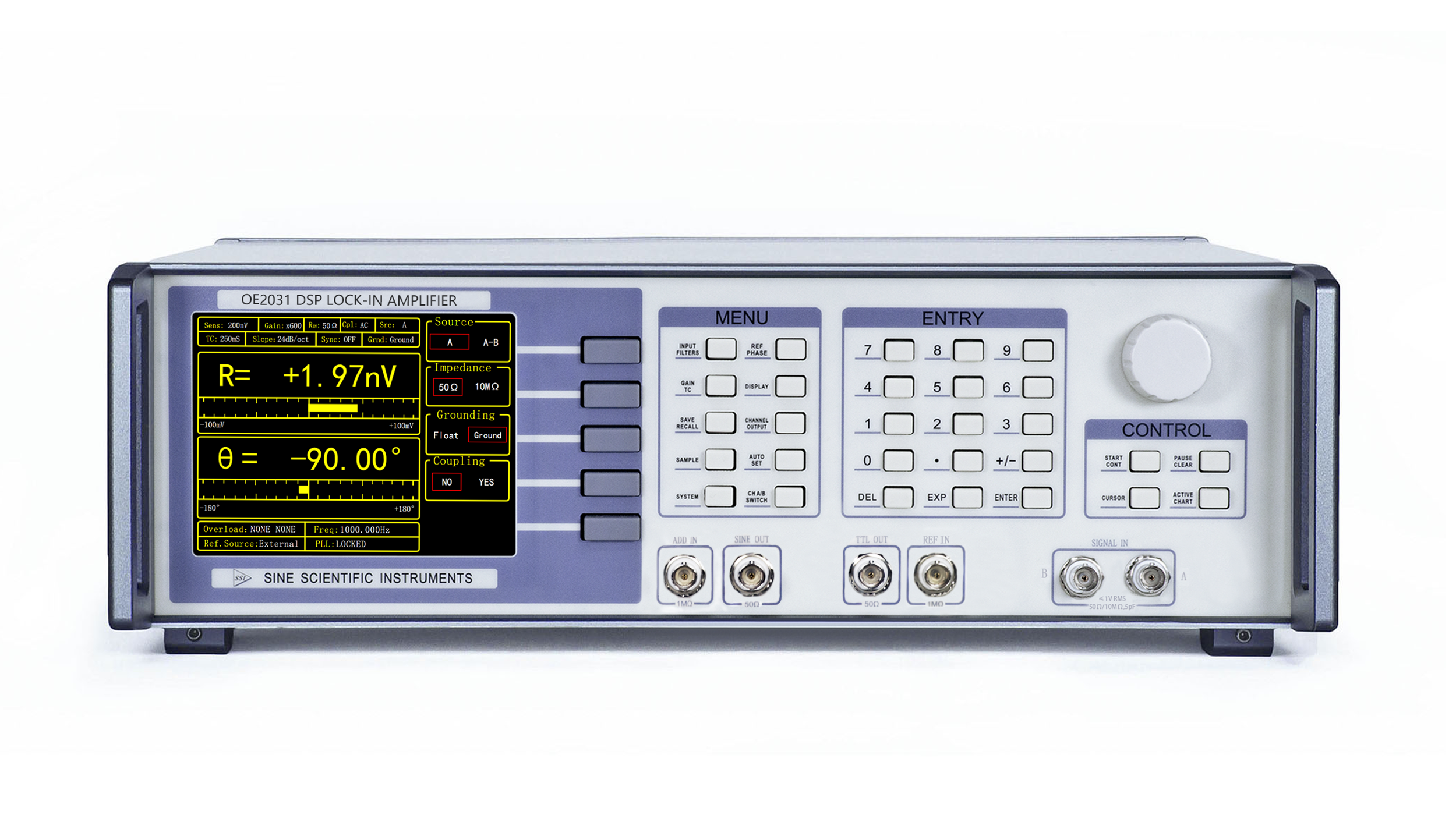
Note: This article uses the Sine Scientific Instruments OE2031 lock-in amplifier to make measurements.
[Overview]
In May 2024, the team of Guolong Chen and Wuyin Jin from Lanzhou University of Science and Technology published an article entitled "Lift-Off Effect of Koch and Circular Differential Pickup Eddy Current Probes" in Chinese Journal of Mechanical Engineering. The team used two planar eddy current probes (Koch and Circular) of the same size with differential pickup structure to compare the lift-off effect, and obtained the distribution of eddy currents of the probes under 0°and 90°crack disturbances by effective element analysis, which finally proved the advantages of the Koch probes in detecting 90° cracks at low lift-off distances.
Eddy current testing (ECT) is one of the common non-destructive inspection methods widely used to detect defects on the surface or inside of metallic materials. This method not only plays a key role in defect detection, but also allows obtaining information about the structure and state of the metal material. When using an ECT system for inspection, the EC probe is an indispensable part, which obtains electrical signals fed back from the sample under test.
In 2015, Chen's team introduced the Koch curve into the design of planar eddy current sensors, proposing a Koch curve excitation and solenoid pickup scheme. 2021, Chen's team designed the excitation coil as a differential structure, proposing a Koch planar eddy current sensor with a parallelism topology. However, in actual probing, there is always a lift-off distance between the probe and the sample, which may cause interference, so in this article, the team further explores the effect of lift-off effect on the signal output of the Koch probe, and will also use a circular coil probe with the same size and winding method, which will be used for the comparison of off-board effect of the Koch probe.
[Sample & Test]
In the article, the transmission characteristics of the material were measured using a lock-in amplifier OE1022, a BP device with a double-gate structure (TG,BG) was used in the study, as shown in Fig. 1(a), a BP film of about 10 nm thick was encapsulated between two hexagonal boron nitride (hBN) flakes, and in order to keep the whole structure flat, a few layers of graphene flakes were used to form the source, drain, and top-gate contacts in order to apply a constant potential shift field in the transmission characterization measurements.
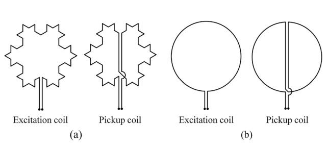
Fig. 1 Coil structure of Koch probe and circular probe
[Measurement Methods & Partial Measurement Results]
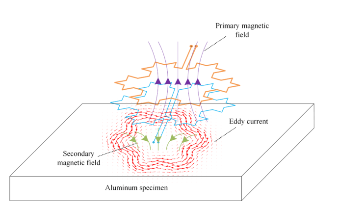
Fig. 2 Principle of operation of the Koch differential pickup probe
When an alternating current is received, the excitation coil of the Koch probe generates the main magnetic field. As the probe approaches the aluminium sample, the sample generates the primary magnetic field and induces eddy currents. Since the eddy currents are also alternating current, according to flute law, a secondary magnetic field is generated around the eddy currents that impedes the variation of the primary magnetic field. A synthetic magnetic field is generated by the interaction between the primary and secondary magnetic fields. Subsequently, the synthetic magnetic field is obtained by means of a pick-up coil and an induced electromotive force is generated. Due to the special winding method of the pick-up coil, the signal outputs of the left and right halves are reversed and can cancel each other out. When there are no defects under the probe, the signal output of the pickup coil reaches zero, i.e. has the property of self-cancellation under ideal conditions. However, when the probe passes over a defect, the signal output of one half of the pickup coil is disturbed. At this point, the total output signal of the pickup coil is no longer zero, so that defect information can be discerned. Due to this property, the negative impact of lift-off effects on the probe can be reduced.
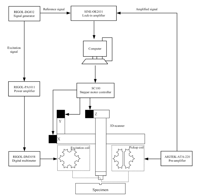
Fig. 3 Schematic diagram of the test system
Firstly, a function generator is used to output a sinusoidal excitation signal with a frequency of 100 kHz and a peak-to-peak value of 300 mV and a TTL reference signal with the same parameters. The output TTL reference signal enters the reference channel of the lock-in amplifier (OE2031, from Sine Scientific Instruments); the sinusoidal excitation signal enters the power amplifier for amplification, and then a multimeter is connected in series in the circuit to monitor the RMS value of the excitation current, and finally it is connected to the excitation coil of the sensor to form a closed loop, which completes the excitation part of the sensor; and then, the induced electromotive force in the pickup coil is acquired, and the pickup coil is connected to the input of the preamplifier to acquire the picked-up electromotive force. The pickup coil is then connected to the input of the preamplifier to amplify the picked-up signal, and then the output goes to the signal input of the lock-in amplifier, which operates with the TTL reference signal in the lock-in amplifier to obtain the real and imaginary signals.
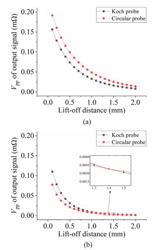
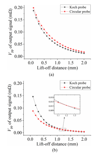
Fig. 4 Experimental results: (a) detection of 0°crack, (b) detection of 90°crack.
Fig. 5 Experimental results: (a) Koch probe, (b) circular probe
Fig. 4(a) demonstrates the output signals when examining a 0° orientation crack. Typically, the value decreases exponentially with increasing distance from the plate, and the response signals output from both probes are almost the same for the same lift-off distance.
For the 90° oriented crack, the experimental results are consistent with the FEA results, as shown in Fig. 13(b). The values of the output signals of both probes decrease exponentially with increasing lift-off distance, while the circular probe's decreases more slowly with increasing lift-off distance. Similar to the finite element results, the lift-off distance has a more pronounced effect on the Koch probe signal than on the circular probe. In other words, the circular probe is more stable at small lift-off distances. The output signal of the Koch probe is significantly larger than that of the circular probe within a certain lift-off distance. At a lift-off distance of 0.1 mm, the Koch probe's output is 66.0% greater than that of the circular probe. As the lift-off distance increases, the Koch probe is no longer larger than the circular probe until the lift-off distance exceeds 1.2 mm and the Koch probe plate distance exceeds 1.2 mm.
Figures 5(a) and (b) show the normalised results of the signal output of the Koch and circular probes, respectively, when a 90° crack is detected. The frequency boost becomes more pronounced as the excitation frequency increases, with 1000 kHz decreasing faster than the other frequencies as the lift-off distance increases.
[Summary]
This study presents a planar differential pickup eddy current probe based on Koch fractal curves. The probe is wound by a differential structure to effectively suppress the lift-off noise during the detection process. A circular differential pickup eddy current probe with the same size is also designed to compare the lift-off effect of these two probes. The following conclusions can be drawn from the finite element analysis and experimental results:
1. At low off-plate distances, 90°cracks interfere more strongly with Koch probes than with circular probes.
2. When the distance from the plate is less than 1.2 mm, the Koch probe is better suited than the circular probe for inspecting cracks in a 90°orientation.
3. The lifting distance of a 1000 kHz signal has a more pronounced effect on the value than 100 kHz and 500 kHz.
[Literature]
[Recommended Products]


