
Keywords: Scanning Tunneling Microscope Lock-in Amplifier Superconducting Thin Films
Note: This article uses the Sine Scientific Instruments OE1022 lock-in amplifier to make measurements.
[Overview]
In 2017, Jinfeng Jia and Canhua Liu of Shanghai Jiaotong University published an article entitled "Development of in situ two-coil mutual inductance technique in a multifunctional scanning tunneling microscope" article, reporting the development of in situ two-coil mutual inductance technique in a multifunctional scanning tunneling microscope.
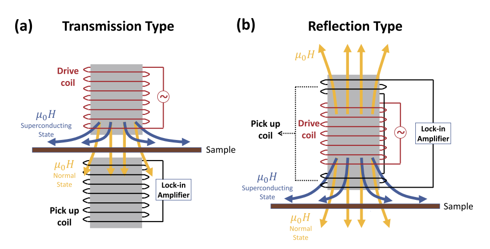
Fig.1 Schematic inductance measurement of a two-coil transformer (a) Transmission type (b) Reflection type.
The yellow and blue arrows indicate the magnetic lines of force emitted by the driving coil when the sample is in the normal and superconducting states, respectively
The article develops a dual-coil mutual inductance device based on a multifunctional scanning tunneling microscope (MSTM), which not only fulfills the functions of a usual scanning tunneling microscope, but also electrically fulfills the functions of an in-situ four-point probe (4PP). Transport measurements were performed using a self-designed four-electrode piezoelectric scanning tube. It is possible to perform all the measurement acquisition for the sample without damaging the superconducting thin film sample. With this technique, it is possible to systematically investigate the superconducting thin films by measuring the electrical and antimagnetic properties of the superconducting thin films at different temperatures (≥ 320 mK) and high magnetic fields (≤ 11 T) in a separate ultra-high-pressure chamber.
[Samples & Tests]
The mutual inductance measurement circuit is shown in Figure 2(a). The drive and detection coils were connected to a Keithley 6221 current source and an OE1022 lock-in amplifier (Sainco Instruments) using coaxially shielded cable. The noise level of the entire measurement system was less than 10 nV. The Lakeshore 350 controller varied the sample temperature by adjusting the output power of a heater near the sample stage. A Cryogenic SMS 100 controller was utilized to generate a magnetic field of up to 11 T in a direction perpendicular to the sample surface. The PC-side control software was written in LabView 2011. Parameter configuration, data acquisition, temperature control, and automatic measurement with magnetic field control are integrated.
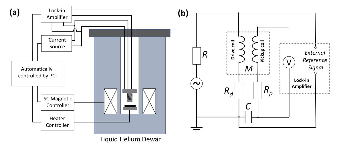
Fig.2 Equivalent circuit of a mutual inductance measuring device.
Figure 2(b) shows the equivalent circuit of the mutual inductance measurement device. A 10 kΩ load resistor R is connected in series with the drive coil to stabilize the phase of an excitation current of less than 200 µA. M represents the mutual inductance between the driver coil and the pickup coil. Rd and Rp represent the resistance of the driver and the detection coil, respectively. In a transmissive (reflective) setup at room temperature, Rd and Rp are approximately 20 Ω (40 Ω) and 5 Ω (7 Ω), respectively. The voltage signal applied to the drive coil also serves as input to the lock-in amplifier REF IN as an external reference signal. The desired phase difference between the output of the detection coil and the reference signal is 90°. However, due to the parasitic capacitance C between the drive and detection coils, a spurious phase shift occurs and the actual phase difference is measured as 90° ± 5°.
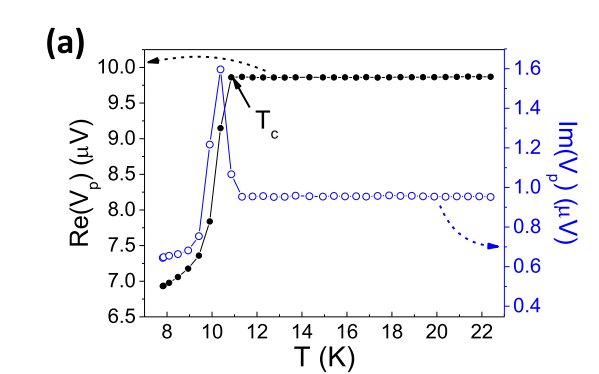
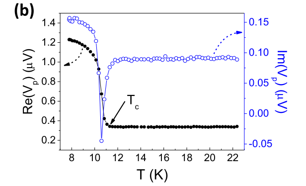
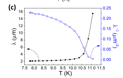
Fig. 3 (a) Mutual inductance measurements for the transmission type (b) Reflection type configuration.
Fig. 3(c) Magnetic penetration depth λ and superfluid density ns / λ-2 results extracted from reflective measurements. The curved arrows indicate each corresponding Y-axis position data set
The measured V-p as a function of temperature in the transmissive and reflective configurations are shown in Figs. 3(a) and 3(b). Both reveal significant superconducting transitions at Tc ∼ 11 K, indicated by the real part of the Vp(T) curve. The peaks (transmissive) or depressions (reflective) in the imaginary part of each Vp(T) curve may be related to energy dissipation due to the vortex-antivortex unbinding mechanism proposed in previous studies. This is to corroborate the existence of the Kosterlitz-Thouless transition mechanism in NbN thin films.
[Summary]
In summary, the authors designed and developed a dual-coil mutual inductance device for multifunctional scanning tunneling microscopy (MSTM) that has four electrodes on a piezoelectric scanning tube. The designed system is capable of efficiently measuring the antimagnetic response of superconducting thin films and STM and 4PP electrical transport measurements. The performance of the dual-coil mutual inductance measurements is experimentally verified on a 10 nm thick NbN film grown on an Nb-doped SrTiO3 substrate, which shows a pronounced superconducting transition at 11 K. The superconducting transition of the NbN film is also demonstrated in the experiments on a Nb-doped SrTiO3 substrate. The intrinsic superconductivity of novel low-dimensional materials can be studied. It is widely used in the study of ultra-thin superconducting films.
In this experimental system, the lock-in amplifier of Saink Instruments is a powerful tool for the detection of weak electrical signals, which provides a stable and effective experimental means for customers in scanning tunneling microscope measurements, and provides a powerful guarantee for the rapid progress of research in this field.
[References]
[Other documents]


