Keywords: Carrier Lifetime Differential Resistance Light Emitting Diode Lock-in Amplifier
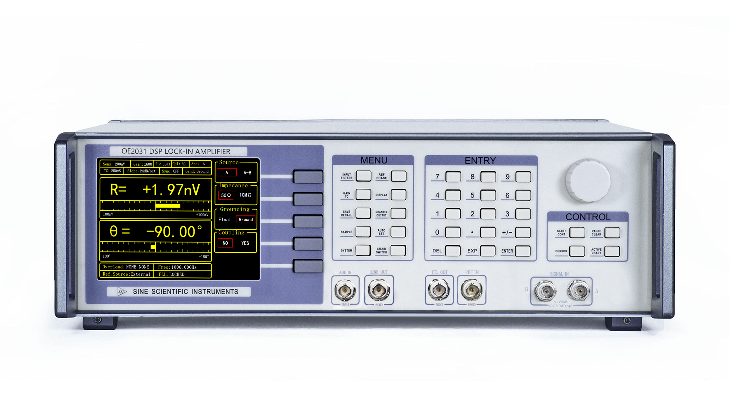
Note: This article uses the Sine Scientific Instruments OE2031 lock-in amplifier to make measurements.
[Overview]
In 2023, the team of Prof. Zhong Chen and Prof. Yijun Lu from the Department of Electronic Science, College of Electronic Science and Engineering, Xiamen University published a paper in IEEE entitled "Study on the Carrier Lifetime of RGB Mini-Light-Emitting Diodes Based on Phase-Sensitive Detection".It is the first time to propose a differential carrier lifetime (DLT) measurement method for electroluminescent LEDs, which has the advantages of high noise immunity and low measurement error with measurement currents as low as 0.1mA, and also obtains the junction capacitance and differential resistance of LEDs.
Based on rate equations and phase-sensitive detection techniques, the team investigated the relationship between differential carrier lifetime and injection current density of red, green and blue mini-LEDs, and found that the differential carrier lifetime of the same LEDs decreases as the injection current density increases, and the differential carrier lifetime of green mini-LEDs decreases faster than that of blue mini-LEDs.
[Sample & Test]
The article uses a lock-in amplifier to phase calibrate the transceiver signal cable of the LED and measure the phase delay at different operating frequencies, thus measuring the differential carrier lifetime of the LED at different injection currents and AC frequencies.

The Sine Scientific Instruments lock-in amplifier (OE2031) receives an external DC input, sums the AC (photodetector input signal) and DC signals, and then uses an internal reference clock to generate a sinusoidal AC voltage signal with an amplitude of 50 mV to drive the LEDs.The light from the LEDs passes through the integrating sphere and the optical fiber, and then is respectively received by the spectrometer and the PIN photodetector. The photodetector converts the light signal into an electrical signal and sends it to a lock-in amplifier, while the spectrometer acquires the spectrum of the LED.
The optical fiber plays the role of splitting the light in the optical path. The response frequency of the photodetector should be much higher than the detection frequency, at least twice as much as the detection frequency, to satisfy the Nyquist sampling theorem. The photodetector bandwidth is 1 GHz, which meets the test requirements. Considering the input noise and operating frequency of the system, the time constant of the lock-in amplifier is uniformly set to 1 ms during the test.

Fig.(a) phase delay of the transceiver signal cable
Fig.(b) differential carrier lifetime of the blue mini-LEDs for different operating frequencies
Fig.(c) differential carrier lifetime of the blue mini-LEDs before and after compensation of the cable phase delay (see Fig. 6 in the article)
As shown in Fig. (a), the phase delays of the transmit and receive signal cables were tested by a DSP lock-in amplifier. It was found that the phase delay of the cables became more severe as the operating frequency increased, while the AC amplitude of the LED light signals decreased. In addition, when the LEDs were operated at a low frequency, the phase difference was small, while the relative error of the system in the phase measurement increased.
As shown in Fig. (b), with the results of the blue mini-LED as representative data, the differential carrier lifetime results fluctuate widely and the test error increases when the system is operated at 100 kHz and 10 MHz; however, the test results are stable in the range of 500 kHz to 1 MHz, which is in line with the frequency range recommended by the phase differentiation method used to determine the differential carrier lifetime.
Fig. (c) shows the differential carrier lifetime results for the blue mini-LED before and after compensating for the phase delay of the cable. The results show that the values of the test results would be much larger if the phase delay of the cable was not taken into account.
[Summary]
The article derives the detection principle of differential carrier lifetime based on the rate equation and the phase-sensitive detection principle of lock-in amplifiers. And it proposes a new detection method of differential carrier lifetime, which uses a lock-in amplifier to lock in the optical signal to be measured and filter out the high-frequency and noise signals, enabling the detection of weak optical signals (which can be as low as 0.1 mA). The measurement method provides higher measurement accuracy than previous methods and is more economical and simpler than the vector network analyzer-based method of measuring LED bandwidth to determine carrier lifetime and the TRPL method.
[Literature]
[Recommended Products]


