Chemical changes such as plating or corrosion cannot be quantitatively determined by surface observation. A small amount of current flows through the sample, measuring its impedance, which is called chemical resistance.
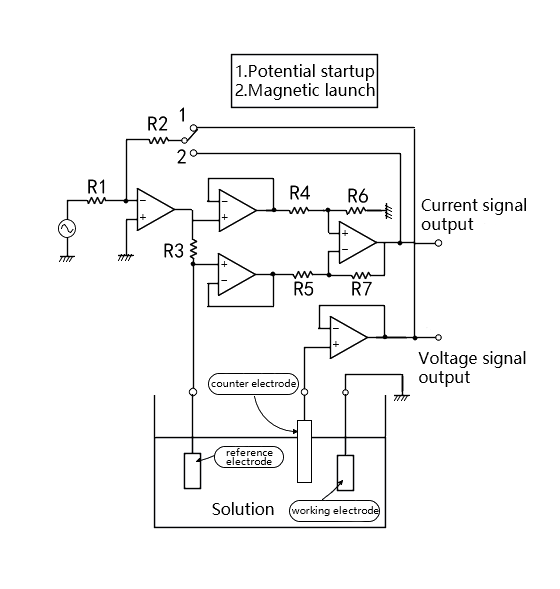
As shown in Figure 1,The chemical impedance is determined by placing two electrodes (a working electrode and a counter electrode) in the electrolyte. In order to detect the solution near the working electrode voltage, a reference electrode is used.

Fig.1 Chemical impedance and drive device
The surface (interface) of the working electrode is the site of the charge transfer reaction. By measuring the impedance here, the properties of the material and the reaction (the state of corrosion or plating in progress) can be understood. Chemical impedance measurement is widely used in the following fields: ① corrosion, corrosion, electroplating materials research; ② Studies on cells, body fluids, skin and membrane of organisms; ③ Evaluation of various batteries, electrolytic capacitors and polymer dielectric materials.
According to the impedance of the sample, the chemical impedance is driven as shown in Figure 1. In the case of constant voltage measurement of the sample, the detection voltage plus feedback (called potential start) of the reference electrode is used, and in the case of constant current measurement, the detection current plus feedback (called magnetic start) is used.
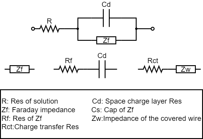
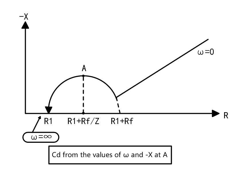
The impedance of the electrochemical system formed by the contact between the electrolyte and the electrode is composed of the following three parts: ① the resistance of the electrolyte R; (2) Capacitance C_d composed of interfacial space charge layer; (3) The impedance Z_f(Faraday impedance) generated by the movement of charge or substance during REDOX reaction. Its equivalent circuit is shown in Figure 2. This is the equivalent circuit of chemical impedance made up of resistance and capacitance. The measurement is carried out according to complex frequencies, as shown in FIG. 3. In each frequency, the real component scale is taken as the X-axis, and the imaginary component X is taken as the Y-axis, forming the so-called Cole-Cole diagram, which can characterize various parameters of chemical impedance.

Fig.2 Equivalent circuit of chemical impedance

Fig.3 Cole - Cole diagram
In general chemical impedance, C is marked below the X-axis as a negative imaginary component. However, in the Cole - Cole diagram, since the objects are only resistors and capacitors, the C mark is above the X-axis and only appears in the first quadrant.
Where a phase-locked amplifier is used for measurement, it is the potential that starts the connection. The voltage of the sample is controlled to be constant, and the detection current signal from the sample is used as the input signal of the phase-locked amplifier, and the impedance is calculated by amplitude and phase.
To measure chemical impedance at complex frequencies, a frequency Response Analyzer called a phase-locked amplifier Digital edition is used for measurement, which is capable of frequency scanning and is more convenient to use.


