

Overview
The OE1311/OE1351 module lock-in amplifier is the latest core technology product, featuring high performance and cost-effectiveness. Utilizing digital modulation, output filter, and high-precision 24-bit analog-to-digital converter (ADC) with the new Zynq architecture, it can accurately and quickly measure effective signal components submerged in high noise. Moreover, the OE1311/OE1351 lock-in amplifier can simultaneously measure the amplitude and phase information of the input signal. It’s comparable to the top technology of the international industry in terms in core parameters such as measurement accuracy, operating frequency range, signal-to-noise ratio, and dynamic reserve. Newly developed functions such as multi-harmonic measurement, oscilloscope, and spectrum analyzer enable the OE1311/OE1351 to meet various scientific and industrial applications.
Input Channel
With the low-noise analog front-end amplifier, the OE1311/OE1351 lock-in amplifier can effectively handle differential or single-ended signals with an equivalent input noise of 5 nV/√Hz. The input impedance is 10 MΩ, and the full-scale sensitivity is 1nV to 5V. Additionally, the OE1311/OE1351 can measure input current signals with a front-end current gain of 10⁶ V/A. The dynamic range exceeds 120 dB, allowing adjustment of the internal programmable gain amplifier based on the amplitude of the input signal to change the system's dynamic reserve. The high-precision 24-bit ADC's sampling rate is 4 MSPS, and the anti-aliasing filter in front of the ADC can effectively prevents signal aliasing.
Reference Channel
The OE1311/OE1351 digital lock-in amplifier's reference signal can be a sine wave or square wave chosen based on the user's needs or an internally synthesized reference signal. When it is set to the internal reference signal mode, the instrument's high-precision oscillator and digital synthesis algorithm generate sine wave signals for multiplication with the input signal, with almost no phase noise impact. The digital phase shifting technology achieves a phase resolution of 1 µdeg. The internal reference signal mode operates in the frequency range of 1 µHz to 1 MHz. The OE1311/OE1351 can also use an external reference signal mode, with sine wave signals and TTL logic levels as external references. The rising edge or falling edge of the external reference signal triggers the internal digital phase-locked loop (DPLL). Based on the reference signal's frequency, the OE1311/OE1351 can detect harmonic signals up to 65535 times the fundamental frequency, but the maximum harmonic frequency can not exceed the operating frequency of 1 MHz.
Filters
The time constant of the OE1311/OE1351 can be set between 1 µs and 3 ks. The output low-pass filter's roll-off rate can be set to 6, 12, 18, 24, 30, 36, 42 and 48 dB/oct. This low-pass digital filter is implemented using an infinite impulse response (IIR) filter structure with a signal processing sampling rate of 4 MHz. The digital modulation method and filter structure of the OE1311/OE1351 ensure higher dynamic reserve (>120 dB), precise phase (absolute phase error <1°), zero DC drift and good orthogonality compared to analog lock-in amplifiers. When the frequency of the input signal is lower than 1kHz, the OE1311/OE1351 can use a synchronous filter to eliminate the harmonic impact of the reference signal, ensuring fast detection of effective low-frequency signals.
Signal Generator
Based on a 16-bit digital-to-analog converter (DAC), the OE1311/OE1351 can generate sine wave signals with a frequency range of 1 µHz to 100/500 kHz. The phase of the signal is related to the instrument's internal oscillator and it’s amplitude can be set. The maximum amplitude of the sine wave signal generated by the OE1311/OE1351 signal generator is 5 Vrms.
Interfaces
The OE1311/OE1351 features a standard 1000 Mbps RJ45 Ethernet port and a RS232 serial port (optional XH2.54-4PIN Port with TTL logic level). Users can effectively use all testing functions of the OE1311/OE1351, including setting reasonable control parameters of the instrument and reading the data measured by the instrument.
Signal Channel
Voltage Input Mode Single-ended or Differential
Full-scale sensitivity 1 nV to 5 V in 1-2-5 sequence
Current gain 106V/A
Input Impedance
Voltage 10 MΩ//10 pF, AC or DC coupled
Current 1 kΩ to virtual ground
C.M.R.R >70 dB to 10 kHz,decreasing by 6 dB/oct above 10 kHz
Dynamic reserve >120 dB
Gain accuracy 0.5% standard, 2% max.
Voltage noise 5 nV/√ Hz at 997 Hz
Reference channel
Inputs
Frequency range 1 uHz to 1 MHz
Reference Input TTL or Sine
Input impedance 10 MΩ
Square reference level VIH>3V, VIL<0.5V
Sine reference signal >2 Hz
>400 mVpp
Phase
Resolution 1udeg
Absolute phase error <1deg
Relative phase error <0.001deg
Drift <0.01 deg/℃ below 10 kHz
<0.1 deg/℃ above 10 kHz
Harmonic detection 2F, 3F, ...nF to 1 MHz (n<65,535)
Acquisition time
Internal reference instantaneous acquisition
External reference (3 cycles + 5 ms) or 40 ms,whichever is larger
Demodulator
Number of demodulators 8
Stability
Digital Output No zero drift for all settings
Display No zero drift for all settings
Analog Outputs <5 ppm/℃ for all dynamic reserve settings
Harmonic Rejection -90 dB
Time constant 1 us to 3 ks, 6, 12, 18, 24,30,36,42 ,48dB/oct rolloff
Synchronization Filter Available below 1 kHz(18,24,30,36,42,48 dB/oct rolloff)
Signal Generator
Frequency
Range 1 uHz to 1 MHz
Accuracy 2 ppm + 10 uHz
Resolution 1 uHz
Distortion -70 dBc
Amplitude 100 uVrms to 5 Vrms (resolution 10 uVrms)
Tolerance 0.5%
Temperature stability 100 ppm/°C
Sine Output Sine signal,output impedance 50 Ω
TTL Synchronous Output 5V TTL/CMOS level, output impedance 200 Ω
AUX Inputs and Outputs
CH 1 and CH 2
Function X,Y,R,θ and harmonics
Amplitude ±10 V
Drive Current ±30mA max
AUX Inputs
Function 2-channel inputs
Amplitude ±10 V, 1 mV resolution
Impedance 1 MΩ
Communication Interface
RS-232(DB-9)
XH2.54-4PIN
1000Mbps Enthernet
Other
Power Requirement
Voltage 12VDC±5%
Power 18W
Dimension
Length 180 mm
Depth 106 mm
Height 44 mm
Scanning Microscope AFM, STM, SPM
Materials Science Carrier mobility, Carrier density, Hall effect, Ultrasonic materials
Transport Measurement Conductivity measurement, Impedance measurement
Noise Represents Noise density, Cross-correlation measurement
Optical Experiment Spectral analysis, Spectral measurement, THz measurement, TDLAS
Sensor Measuring Gyroscope, Photoelectric sensor, Resonator, Accelerometer
Magnetic Sensor SQUIDs, NV color center, Atomic Magnetometer, VSM
Biomedical Microfluidic
PC Software
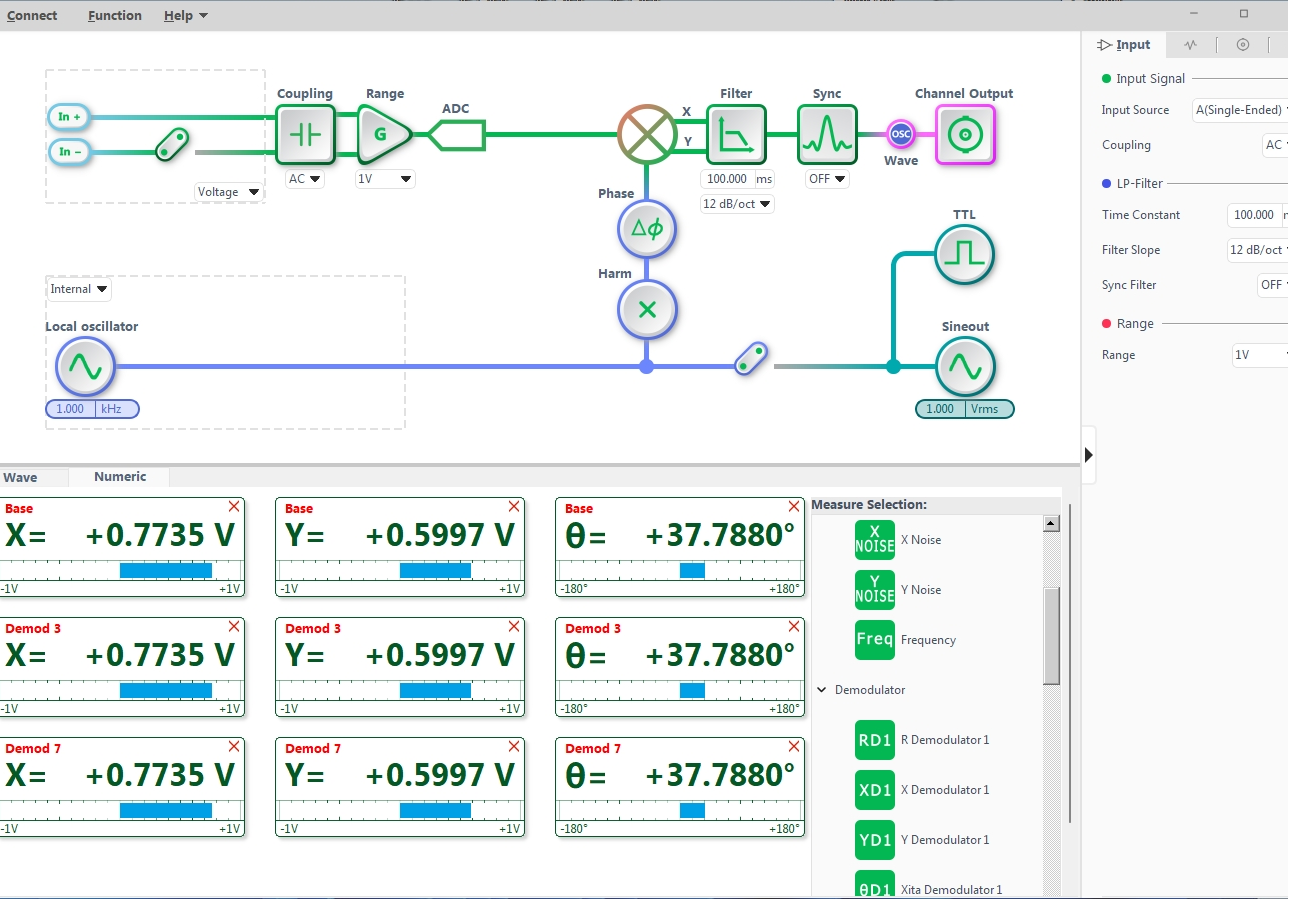
The accompanying graphical upper computer software includes quick graphical buttons and rich graphical operation functions. Additionally, the software provides clear numerical and waveform display functions, allowing real-time display of measurement data. Measurement results can be output and saved in CSV files for subsequent analysis by professional software, making testing more convenient. We also fully support Python, MATLAB and LabVIEW application programming interfaces (API).
Oscilloscope
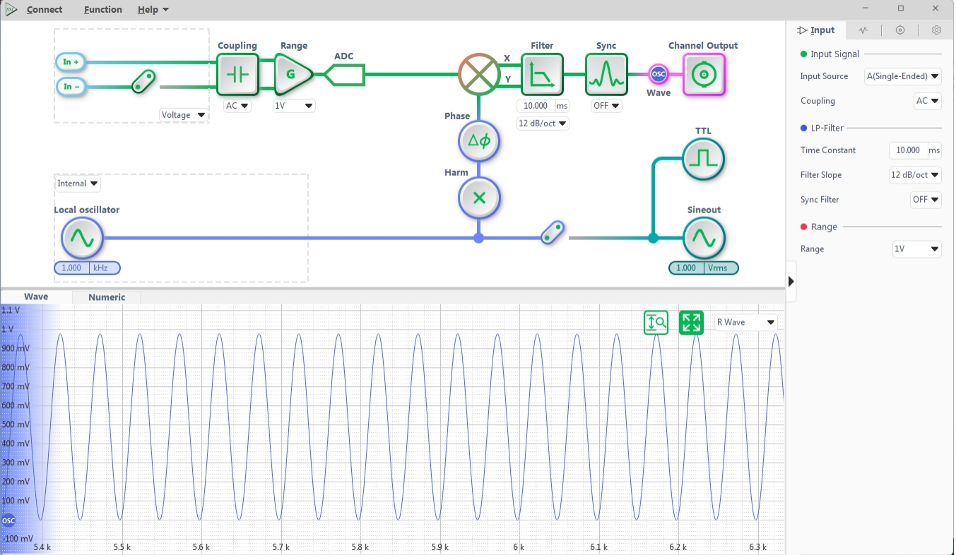
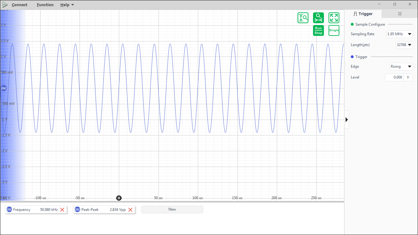
The oscilloscope features a 4 MSa/s analog input channel with 2 MHz analog bandwidth, 5 Vrms input voltage range, and user-configurable AC/DC coupling and 10 MΩ impedance.
Spectrum Analyzer
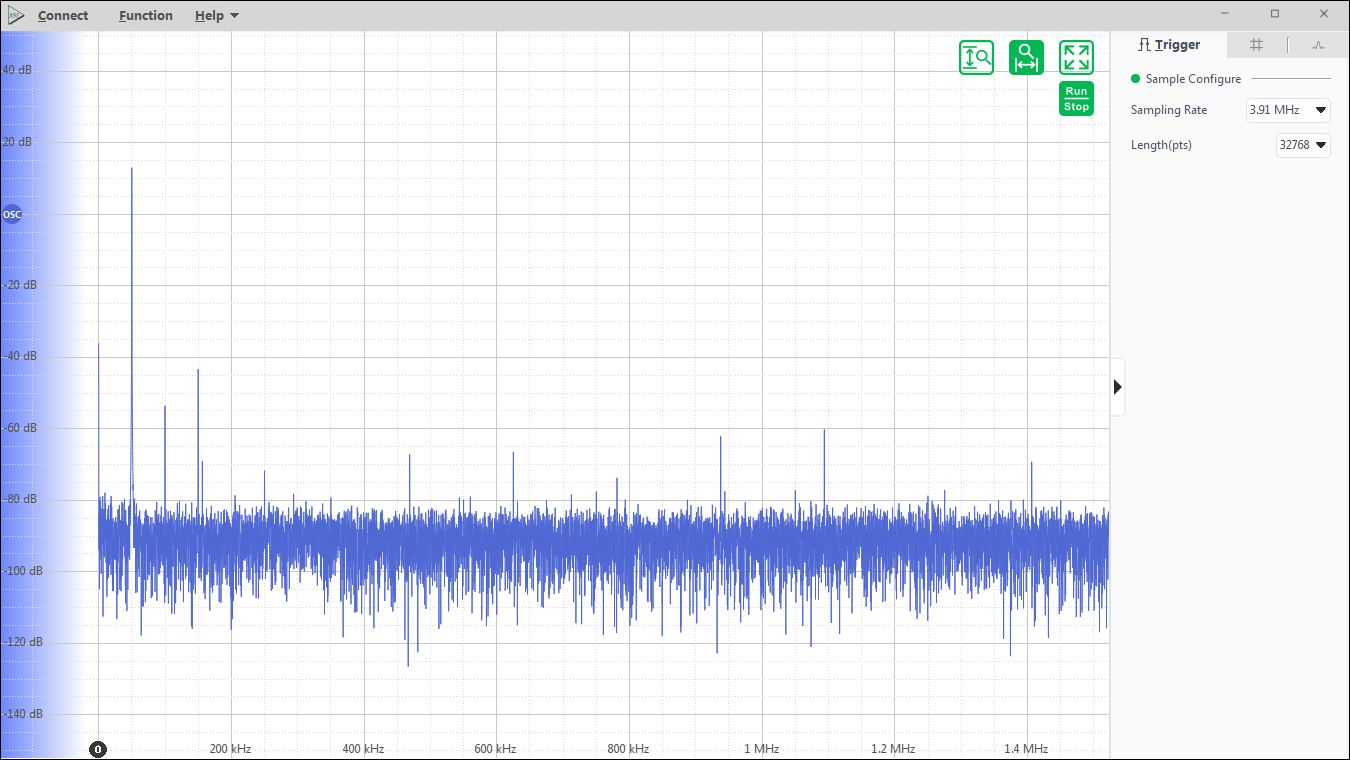
Spectrum analyzers can observe DC to 2 MHz input signals in the frequency domain. Simultaneous resolution bandwidths are as low as 1 Hz with a minimum span of 100 Hz.
Multi-Demodulator
Conventional lock-in amplifiers can only measure the fundamental frequency or a certain harmonic component at the same time. Therefore, for some cases that require the amplitude and phase of multiple frequency components at the same time, traditional lock-in amplifiers are unable to meet the measurement requirements.The digital side of the OE1311/OE1351 combines FPGA and ARM technology to realize higher processing bandwidth and more flexible digital architecture, with a digital processing accuracy of up to 48 bits, allowing up to 8 easy frequency analysis signal inputs at the same time, and 8 demodulators that can be freely configured for amplitude and phase to realize free combination. demodulators can be freely configured amplitude and phase to realize free combination.
PID Controllers
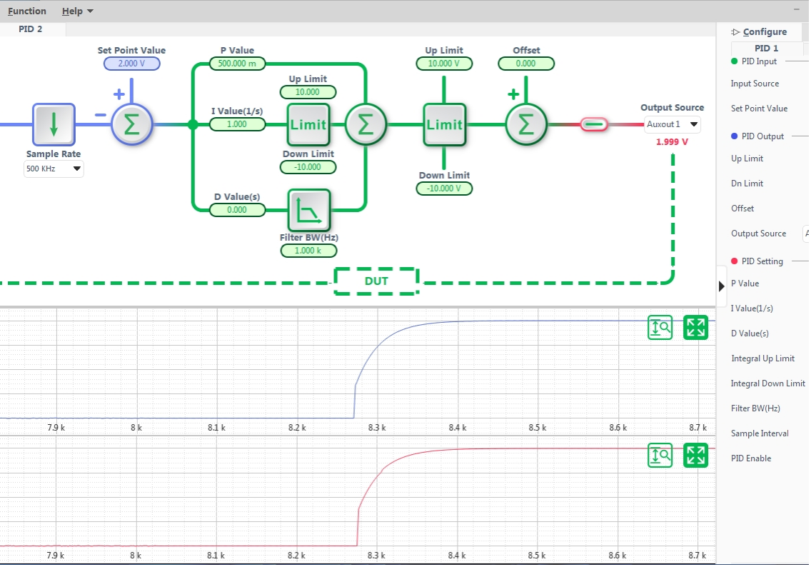
The OE1311/OE1351 features a built-in independent 2-channel digital PID controllers, the PID sampling rate can reach up to 4 MSa/s. The 2 PID controllers are tightly connected to the lock-in amplifier and can take all input interfaces and measurement signals as inputs and provide feedback via signal amplitudes, phase shifts, output interfaces and more. The PID provide stable and accurate control, can handle changes in system dynamics effectively, making them suitable for a wide range of applications.
