

Product Description
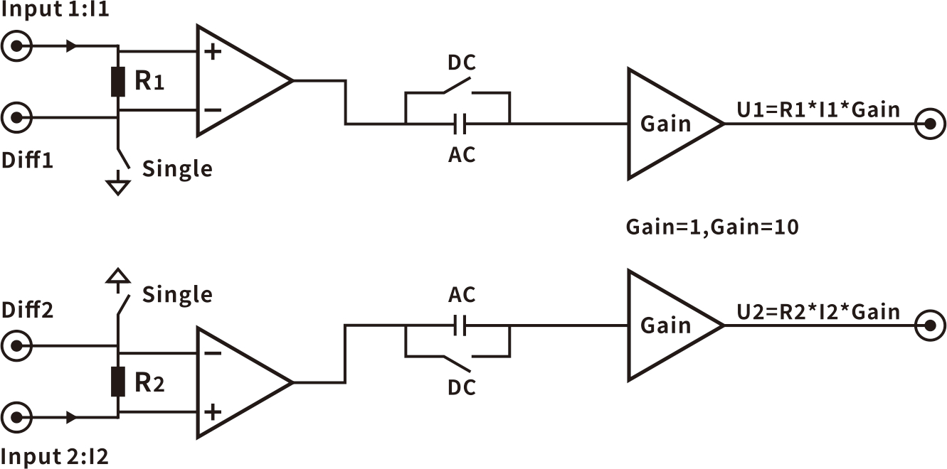
The OE4101 is a transimpedance current pre-amplifier that utilizes a negative feedback structure to convert input current to voltage using a feedback resistor and to control amplification.
The OE4102 detects current by measuring the voltage drop across a resistor on the input current channel, amplifies and outputs a voltage signal proportional to the measured current.
OE4102 High Frequency Dual Channel Current Pre-amplifier
100fAV/√Hz Input Current Noise
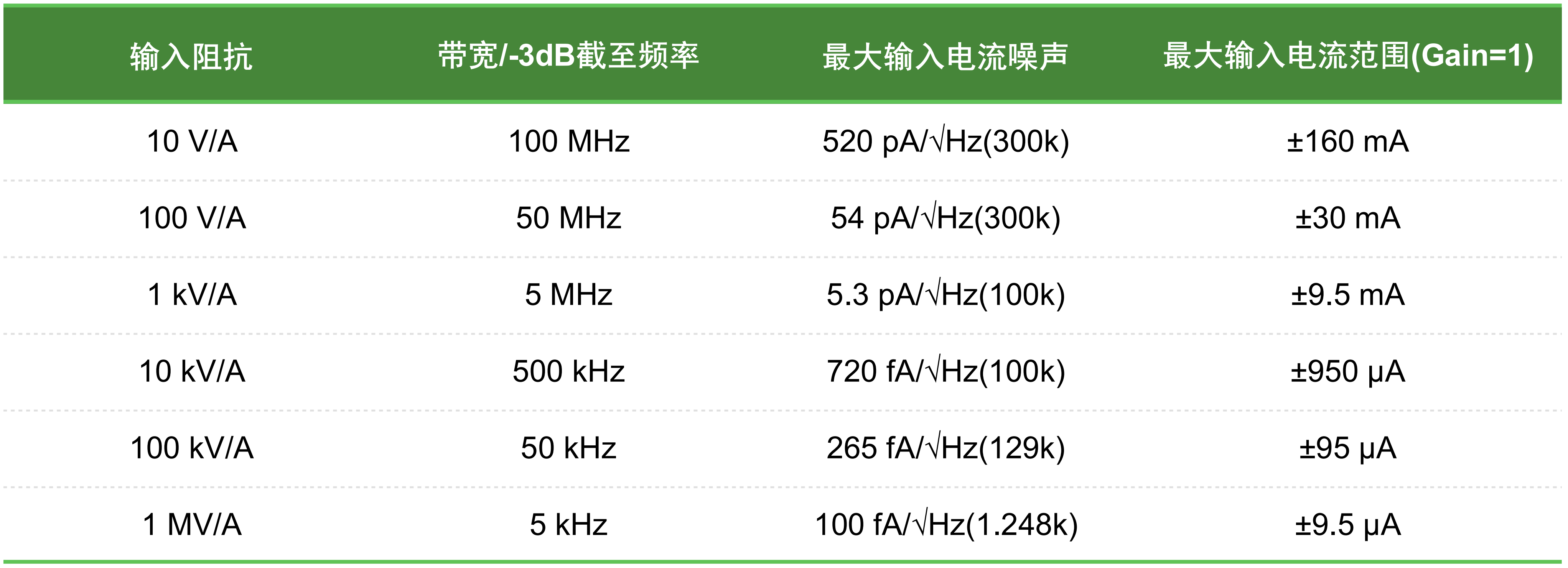
10V/A,100V/A,1kV/A,10kV/A,100kV/A,1MV/A Current Gain
1,10 voltage gain
Single-ended or differential inputs
Principle Block Diagram

Product Specification
Dimension 102*162*49(mm)
Weight 0.3kg
Storage temperature -20 ℃ to 65 ℃
Operating temperature 5 ℃ to 40 ℃
Power supply 12V/1A
Maximum power consumption Approx 7.9W
Specification
Size 102*162*49(mm)
Weights 0.3kg
Storage Temp. -20°C to 65 °C
Work Temp. 5°C to 40°C
Specification Temp. 25°C
Using Power 12V/1A
Power Wastage 7.9W max
Connection Ports 4 SMB inputs
2 SMB outputs
DC 5.5-2.1 mm input terminals
Caution: Unless otherwise noted, all specifications apply only to units after 30 minutes of preheating.
Performance Parameters
Scope of supply
MIN 9V
RATED 12V
MAX 15V
Inputs
Input Mode Single-ended or Differential
Current Range ±160 mA
Current Noise 100 fA/√Hz
Voltage Noise 7 nV/√Hz(10kHz)
Bias Voltage <±1mV
Leakage Current 2 pA
Impedance Range 10 V/A-1 MV/A (Z//12pF)
Coupling Method
DC coupling DC-100 MHz
AC coupling 290 kHz-100 MHz
Common-mode ±9.5V
Outputs
Output Mode Single-ended
Voltage Gain Gain=1,Gain=10
Output Voltage ±9.5V max
Frequency Response DC-100 MHz
Impedance 50Ω
Gain Accuracy 1% typical, 5% max
Gain parameters

Caution: All parameter values in the table are typical and will vary depending on the source capacitance, input signal swing, and capacitive loading at the output of the amplifier.
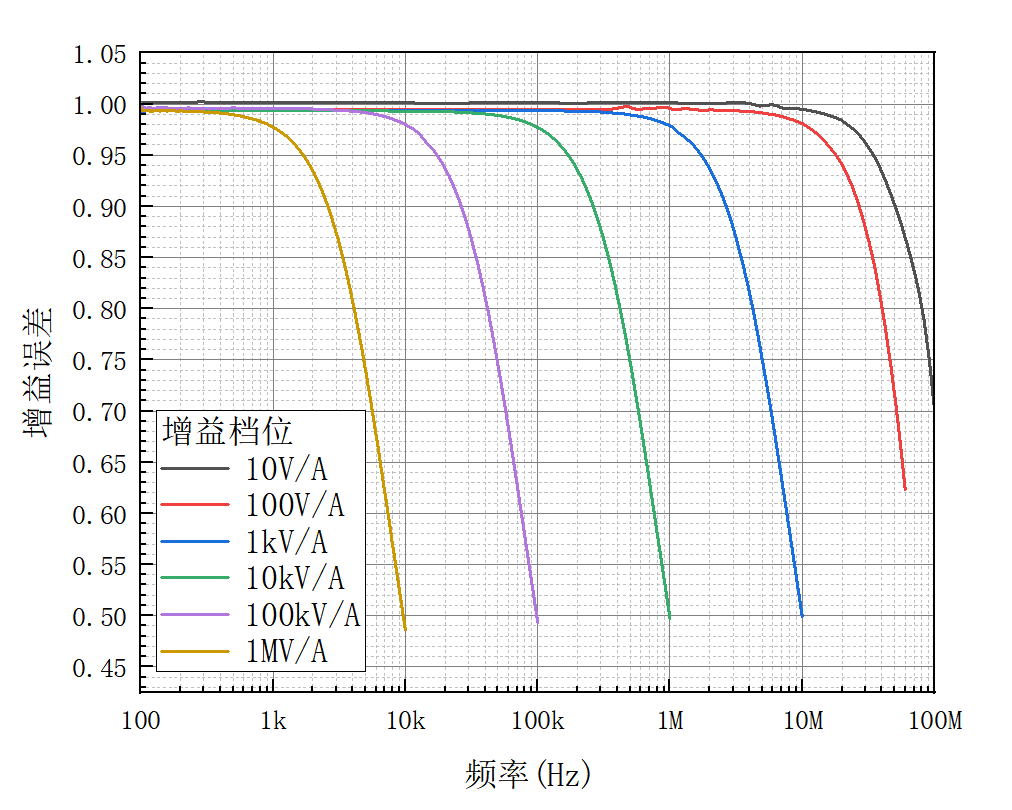
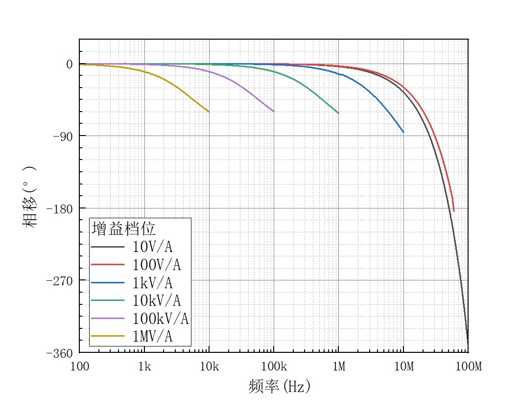
Test conditions: Supply voltage = 12V, ambient temperature = 25°C; input current 14mA-0.5μA; OE4102 gain steps 10V/A-1MV/A, DC-coupled, single-ended input, Gain = 1.
Note: [1]. 10V/A stall input capacitance Cs=100pF.

Fig.1 Gain error-frequency curve
![]()

Fig.2 Phase shift-frequency curve


