The Hall effect is a kind of electromagnetic effect. When the current passes through the semiconductor perpendicular to the external magnetic field, the carriers are deflected, and an additional electric field is generated perpendicular to the direction of the current and the magnetic field, thereby generating a potential difference between the two ends of the semiconductor. The phenomenon is the Hall effect. The Hall effect is widely used in material characterization and magnetic field sensing.
Material Characterization
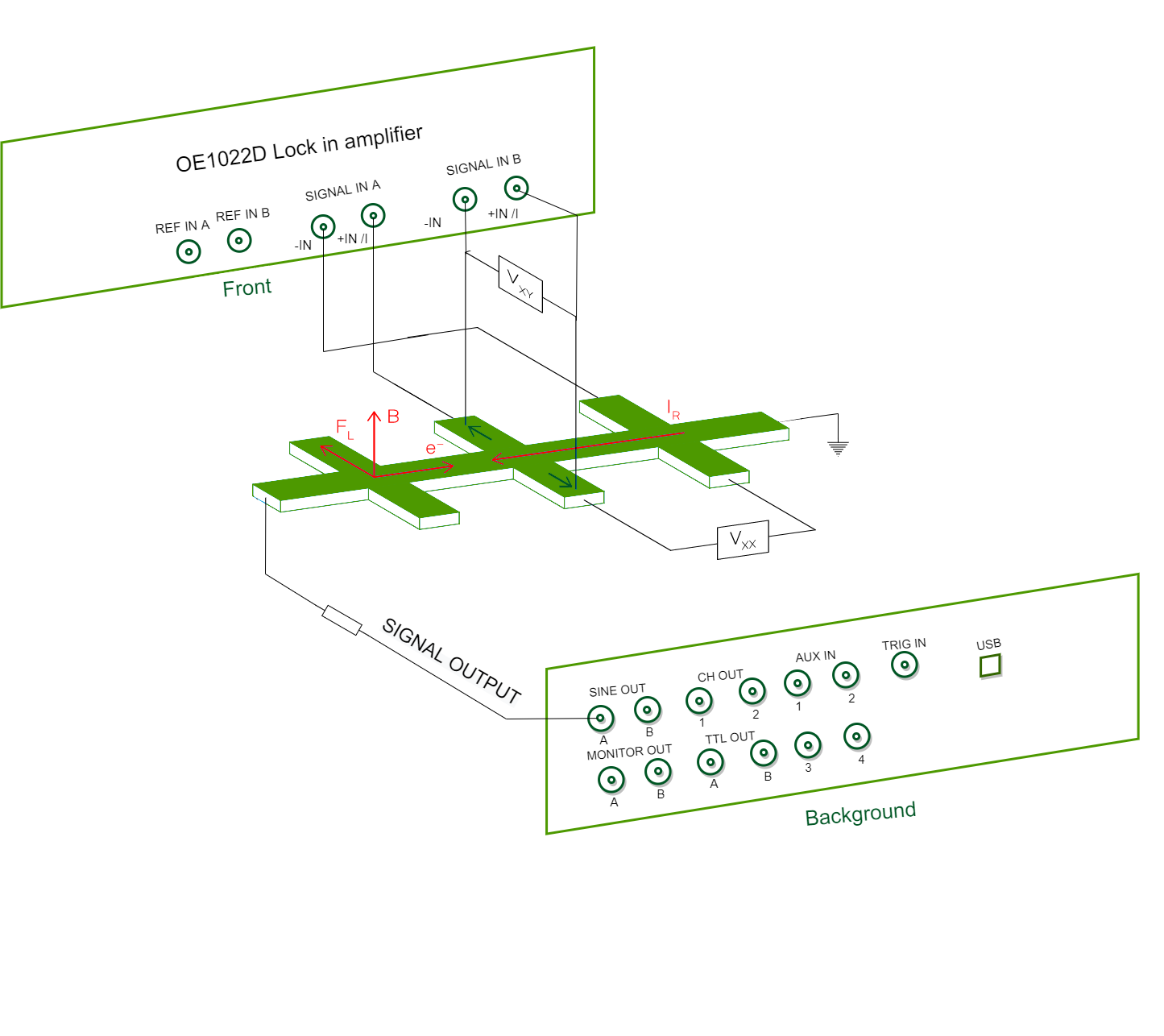
In material characterization applications, the material is placed in a known magnetic field B. At the same time, the Hall voltage V XY (see figure below), the voltage V XX across the sample and the current IR through the material are measured . From these measurements, we can infer material properties such as carrier density, carrier polarity, carrier mobility and the material's electrical conductivity.
This technique can also be used to measure the quantum Hall effect and various derivative effects such as integer, fractional, spin, inverse spin, etc., to measure new physical properties of two-dimensional electron gas (2DEG) materials.
Magnetic field induction
When the material properties are known, the Hall effect can be used to infer the strength of external magnetic fields over many orders of magnitude. Measurements can be performed by applying a DC voltage to the sample, but AC measurements are generally faster and more accurate. Other benefits of AC measurements include greater accuracy and sensitivity, enabling higher signal-to-noise ratio (SNR) over a larger measurement range.

Fig 1.Measuring Hall voltage structure diagram
As is shown in the figure 1, the measurement requires the use of two lock-in amplifiers. Cyntech OE 1022 D is a dual-channel lock-in amplifier with 2 independent synchronized lock-in units . One lock-in amplifier can meet the measurement needs.
(Denoted as LIA in the figure A channel ) provides a constant AC voltage to generate a current in the sample. Typically, the current is assumed to remain constant during the measurement by simply placing a current-limiting resistor, RL, that is much larger than the sum of all other resistors in the circuit. A more accurate measurement can be achieved by measuring the current through the sample. Lock-in Amplifier 1 measures the Hall voltage V XY , while Lock-in Amplifier 2 (denoted LIA in the diagram) Channel B ) Measure the voltage V XX across the sample .


