

Overview
The OE2012 dual-channel lock-in amplifier is the latest core technology product, featuring exceptional high performance and wide bandwidth measurement capabilities. This instrument is based on digital modulation technology and is equipped with a 24-bit high-precision analog-to-digital converter (ADC) and 16-bit high-speed digital-to-analog converter (DAC). With the newly launched LIUXI-architecture, it can accurately, quickly, and flexibly detect effective signal components hidden in strong noise.
The OE2012 has 2 independent and synchronized input channels, capable of simultaneously measuring the amplitude and phase information of two input signals. It achieves international leading levels in key performance indicators such as measurement accuracy, operating frequency range, signal-to-noise ratio, and dynamic reserve. Additionally, the newly added multi-harmonic measurement, oscilloscope, spectrum analyzer functions, and PID control capabilities make the OE2012 widely applicable to various needs in scientific research and industrial fields.

Block Diagram of OE2012
Input Signal Channel
The OE2012 is equipped with a low-noise analog amplifier that efficiently processes single-ended or differential signals, with an equivalent input noise as low as 2.5 nV/√Hz. The input impedance of this channel is 10 MΩ, and the full-scale range is from 1 nVrms to 5 Vrms. Furthermore, the signal input channel uses a high-precision 24-bit ADC, achieving a dynamic range over 130 dB.
Output Signal Channel
The signal output ports of OE2012 is based on a 32 MSPS 16-bit DAC, capable of generating high-precision sine wave signals in the frequency range of 1 Hz to 250 kHz, with adjustable DC offset. The signal amplitude range is from 0.1 Vrms to 5 Vrms, and the DC offset range is ±5 Vdc. For external devices requiring bias voltage, such as electro-optic modulators, the OE2012 can drive devices directly without the need for additional level conversion amplifiers. The output signal phase is synchronized with the instrument's internal oscillator. It can be independently set for phase offset.
Additionally, the OE2012 supports AM/FM/PM modulation functions, allowing users to perform modulation control of the system.
Reference Signal Channel
The reference signal of the OE2012 can be selected as either a sine wave or square wave signal based on user requirements, or it can use an internally digitally synthesized reference signal. When the OE2012 is set to internal reference signal mode, the instrument's internal high-precision oscillator and digital synthesis algorithm generate a sine wave signal for multiplication with the input signal, with the internal reference signal being nearly unaffected by phase noise. Through digital phase shifting technology, the phase resolution of the internal reference signal can reach 1 μdeg.
When the OE2012 operates in external reference signal mode, it accepts sine wave signals or TTL logic levels as external reference signals, which are locked by the internal digital phase-locked loop. Based on the frequency of the reference signal, the OE2012 can detect signals at the fundamental frequency and its harmonics, detecting up to 10,000 times the fundamental frequency. But it provided that the maximum harmonic frequency does not exceed the upper limit of the instrument's measurement bandwidth.
Digital Demodulator
The OE2012 has 8 synchronized demodulators, which can be independently controlled. The time constant of the OE2012 can be flexibly set within the range of 100 ns to 3 ks, allowing users to customize the time constant according to their needs. The filter's roll-off rate can be selected from 6 to 48 dB/oct in 8 steps. Using digital modulation technology and advanced filter structures. The OE2012 offers higher dynamic reserve (>130 dB), more precise phase (absolute phase error < 1°), zero DC drift, and excellent orthogonal performance compared to traditional analog lock-in amplifiers. Additionally, the OE2012 provides an optional synchronous filter that can quickly eliminate the effects of signal harmonics, ensuring that the instrument accurately detects low-frequency signals while responding rapidly.
Communication Interface
The OE2012 includes USB 2.0, 1000 Mbps RJ45 Ethernet port, WIFI network interface, RS232 serial port, and GPIB interface. Through these interfaces, users can effectively utilize all testing functions of the OE2012 on a controlling computer, setting reasonable control parameters and reading the data measured by the instrument.
Color Display Screen
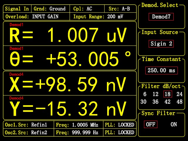
The OE2012 features a 5.6-inch TFT color display with a resolution of 640×480, serving as the main user interface, allowing full independent control of the instrument via keyboard. On the display, users can easily heed parameters such as demodulator X, Y, R, θ, and configure various basic settings like filter constants, making the operation intuitive and convenient.
Input Signal Channel
Input Channel Number 2
Input Mode
Voltage Single-ended or Differential
Current Single-ended
Full-Scale Sensitivity 1 nV to 5 Vrms
Range Levels 2mV to 5V, total 7 levels
Input Coupling Mode DC or AC coupling
Input Impedance 10 MΩ || 25 pF (Voltage)
100Ω or1 kΩ (Current)
Input Shield Grounding Grounding or 10 kΩ floating
Dynamic Reserve >130 dB
Gain Accuracy 0.5% typical, 1% max
Input Voltage Noise 3.5nV/√Hz(f ≥ 1 kHz)
2.5 nV/√Hz(f ≥ 10 kHz)
Input Current Noise 20 fA/√Hz(f = 97Hz)
ADC Bit 24 bit
Reference Signal Channel
Reference Channel Number 2
Reference Signal
Frequency Range 10 μHz – 250kHz
Supported Waveform Square or sine wave
Input Impedance 1 MΩ
Reference Levels
Square 3V<VIH<5V, -0.1V<VIL<0.5V
Sine 300 mV < Vpp < 10 V
Phase
Resolution 1.0 μdeg
Phase Error ±0.5 deg typical, ±1 deg max
Temperature Drift < 200 ppm/℃
Harmonic Detection 1-10000F (nF < 1.5 MHz)
Acquisition Time
Internal Reference Instantaneous acquisition
External Reference 10 or 100 signal cycles
Oscillator
Oscillator Number 2
Oscillator Parameters
Accuracy 0.3 ppm
Temperature Stability 0.5 ppm/℃
Aging Rate <1 ppm/year
Phase Noise -145 dBc/Hz (@1kHz)
Output Signal Channel
Output Channel Number 2
Frequency Range DC – 250kHz
Frequency Accuracy 2 ppm + 1 μHz
Frequency Resolution 1 nHz
Sine Amplitude 0.1 μVrms to 5 Vrms
Accuracy 0.5% typical, 2% max
Resolution 0.1 μVrms
Driving Current ± 80 mA max
Temperature Stability <200 ppm/℃
Output Impedance 50 Ω
Adjustable DC Offset -5 VDC to 5 VDC
Synchronous Output 3.3V TTL/CMOS level
output impedance 50 Ω
Additional Features AM/FM/PM modulation output
DAC Parameter 16 bit, 32 MSPS
Demodulator
Demodulator Number 8
Demodulator Bit 64 bit
Input Source Select 2 input channels selectable
Time Constant 100ns - 3ks
Measurement Bandwidth 50 μHz – 1.6 MHz
Filter Slope (dB/oct) 6, 12, 18, 24, 30, 36, 42, 48
Synchronous Filter <1000 Hz effective
Auxiliary Inputs/Outputs
AUX Input
Function 4-channel input
Amplitude ±10V, 0.1 mV resolution
Input Impedance 1MΩ
ADC 16 bit, 150 kSPS
AUX Output
Function 4-channel output
Amplitude ±10V, 0.1 mV resolution
Driving Current ±30 mA max
DAC 16 bit, 500 kSPS
Communication Interfaces
RS-232 DB-9 female interface
USB2.0 480 Mbpshigh-speed interface
Ethernet RJ45-1000Mbps
WIFI wireless network interface
GPIB IEEE-488.2interface
Others
Power Supply
Voltage 220-240 V AC
100-120 V AC(optional)
Power 50 W typical, 70 W max
Power Noise Suppression 70dB@1MHz
Dimensions 448mm×532mm×148mm
Weight 12 kg
Scanning Microscope AFM, STM, SPM
Materials Science Carrier mobility, Carrier density, Hall effect, Ultrasonic materials
Transport Measurement Conductivity measurement, Impedance measurement
Noise Represents Noise density, Cross-correlation measurement
Optical Experiment Spectral analysis, Spectral measurement, THz measurement, TDLAS
Sensor Measuring Gyroscope, Photoelectric sensor, Resonator, Accelerometer
Magnetic Sensor SQUIDs, NV color center, Atomic Magnetometer, VSM
Biomedical Microfluidic
PC Software
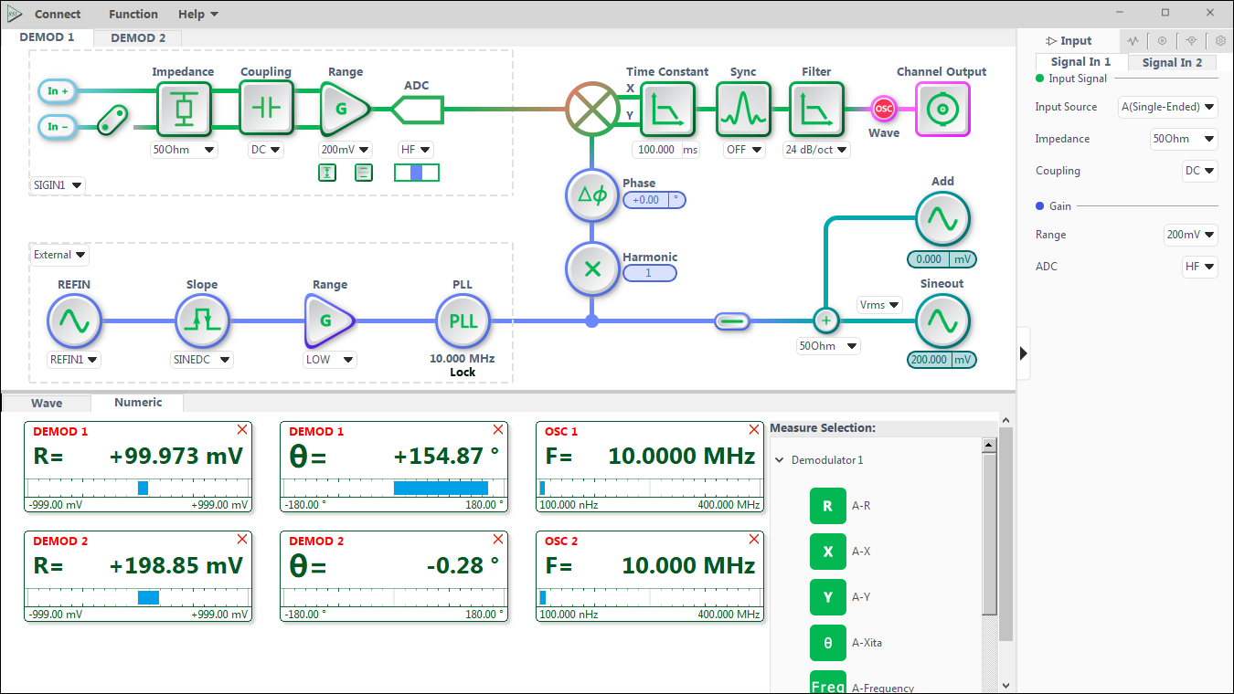
The OE2012 provides professional PC software that allows configuration of each demodulator, input channel, and output channel through schematic diagrams or control panels, combining professionalism and practicality with simplicity and intuitiveness. The software features clear numerical display and real-time waveform display functions. Users can save the measurement results exportable as CSV files for subsequent analysis using professional software, enhancing the ease of testing. Furthermore, we fully support application programming interfaces (API) in Python, MATLAB, and LabVIEW.
Oscilloscope
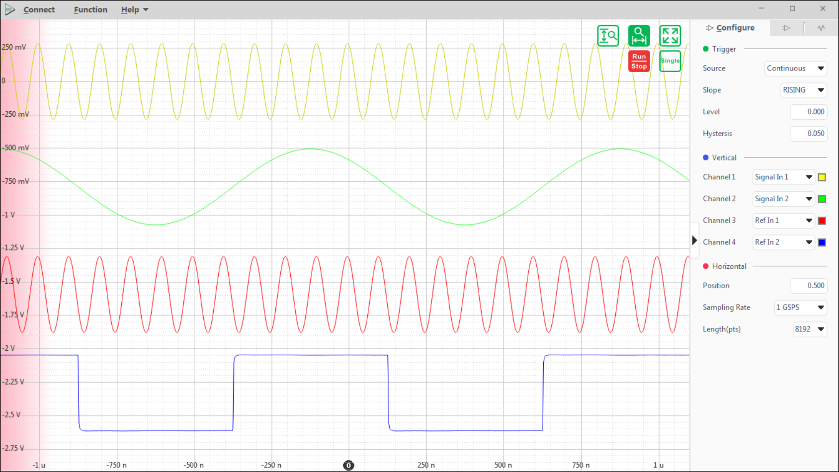
The oscilloscope function features 2 signal channels, selectable for signal input, reference input, signal output, and auxiliary input/output, providing various triggering methods for real-time display of time-domain signals. Each channel has a maximum sampling depth of 65,536 and adjustable sampling durations from 65 µs to 1 s.
PID Controllers
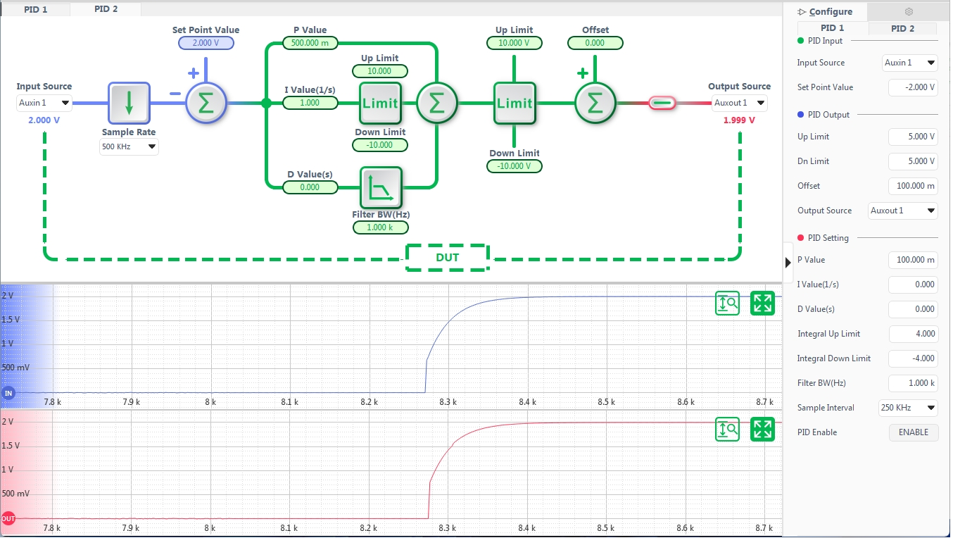
The OE2012 has an internal independent 2-channel digital PID controller with a maximum sampling rate of 4 MSPS. The PID controller is closely linked with the lock-in amplifier, controlling the output signal's amplitude, phase, frequency, and other signals based on the measurements from the demodulator, achieving precise control of multiple parameters.
Parametric Scanner
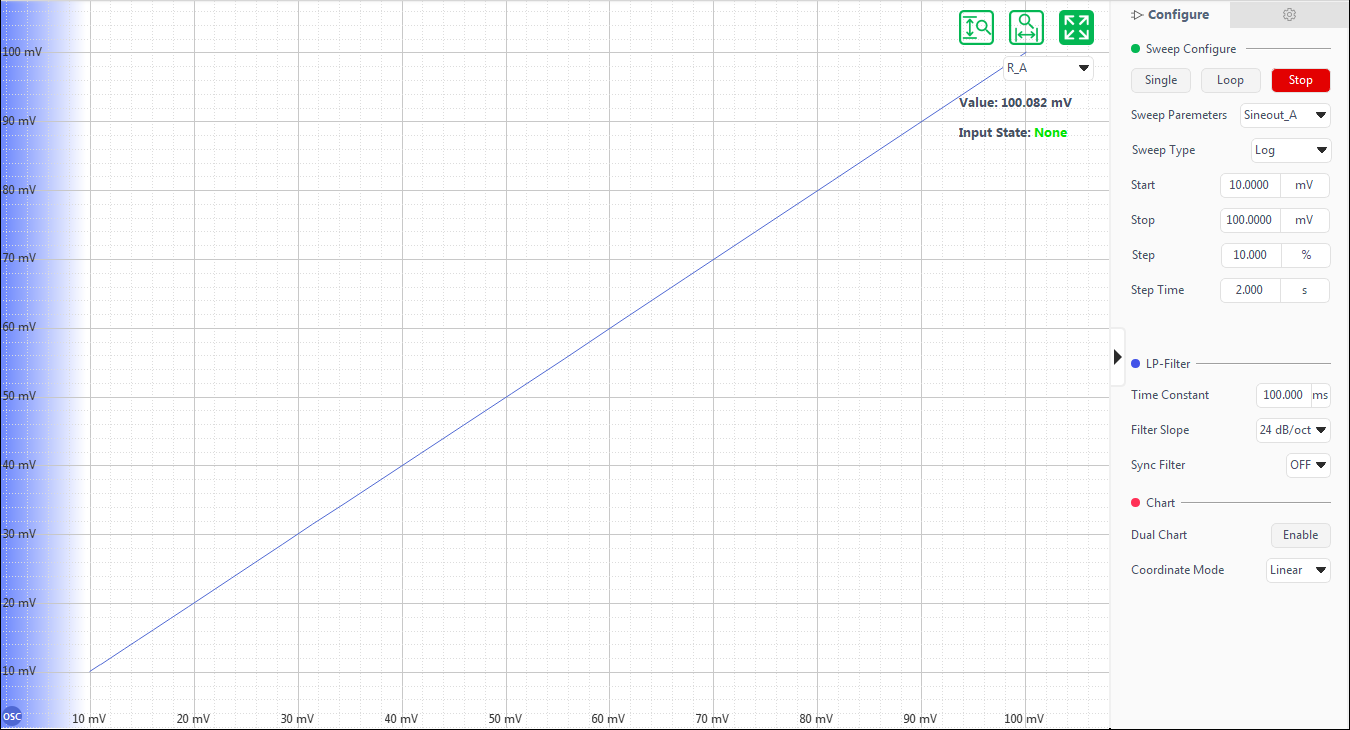
The parameter scanner provides users with convenient quick scanning capabilities, allowing for the instant plotting of frequency response, amplitude response curves, and offering single or loop scanning modes.
FFT Spectrum Analyzer
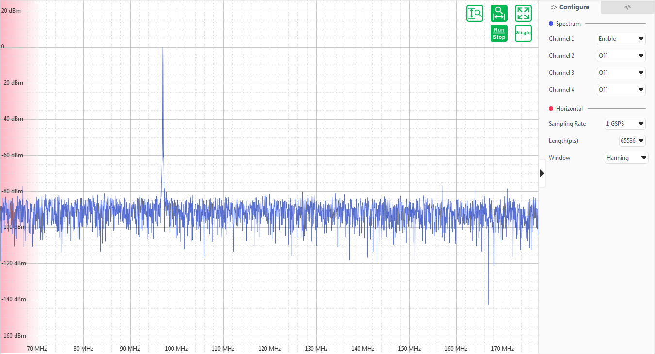
The FFT spectrum analyzer analyzes the frequency domain information of signals based on waveforms captured by the oscilloscope. Depending on the sampling rate and sampling depth, the frequency resolution range of the spectrum analyzer is approximately 1 Hz to 31 kHz.
