

Input Channel
OE2041 detects an input signal in a single-ended mode or a differential voltage mode. With an ultra low-noise pre-amplifier, the input noise is as low as 6 nV/√Hz@100 kHz. The input impedance is 50 Ω or 10 MΩ and the full-scale input voltage sensitivity ranges from 1 nV to 1 V. Besides, designed to eliminate power frequency interference. A programmable gain amplifier is used to adjust the dynamic reserve of the system, so that OE2041 can keep a high dynamic reserve of 120 dB.The high-precision 14-bit ADC has a sampling rate of 250 MSPS, and the excellent anti-aliasing filter in front of the ADC can effectively prevent signal aliasing.
Reference Channel
The reference signal can work in external mode or internal mode. In internal mode, a precise and stable internal oscillator generates sine wave as an internal reference that is multiplied by the input signal. This internal signal is without any phase noise. With the digital phase-shifting technique, the phase resolution of the reference signal is 0.001 deg. OE2041 can work at any fixed frequency from 1 mHz to 60 MHz in this mode.In external mode, the reference signal can be a sine wave or a TTL pulse or square wave. The rising or falling edge of the external reference signal triggers the Phase Lock Loop (PLL) to lock the external signal. Based on the frequency of the reference signal, can demodulate multiple harmonics and arbitrarily frequency input signal. The maximum harmonic signal frequency can reach 32,767 times the fundamental frequency, and the maximum harmonic frequency cannot exceed the maximum operating frequency of the instrument by 60 MHz.
Digital Demodulator and Output Filter
The key component of the OE2041 is the digital demodulator. Compared to traditional analog lock-in amplifiers, the OE2041's internal digital demodulator effectively rejects the measurement errors caused by DC drift and offset. In addition, by optimizing the multiplication of the internal coherent signal of the digital demodulator, the calculation error is minimized so that the instrument can accurately detect the input weak signal. Time constants of the output low-pass filter from 30 ns to 4.4 ks can be selected with a choice of 6,12, 18, 24, 30, 36, 42 and 48 dB/oct rolloff. This low-pass digital filter is implemented using a high performance digital filter with a sample rate of 250 MHz. The digitaldemodulation and the low-pass filter used in OE2041 guarantees a high dynamic reserve (>120dB), accurate phase (absolute phase error <1 deg). Moreover, when the frequency of the input signal is lower than 200 Hz, A synchronous filter can be used to eliminate the harmonic influence of the reference signal, ensuring that OE2041 can detect a lowfrequency signal quickly and effectively.
Display
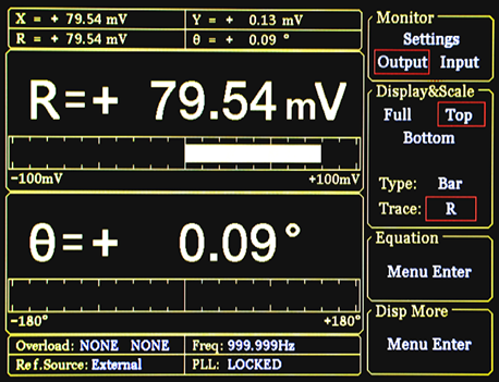
OE2041 has a 5.6-inch 640 x 480 color TFT-LCD. The measurement results of OE2041, such as X, Y, R, and θ, are shown in numerical form and bar graph on the display.In X-Y chart, OE2041 shows the trend of measurement results over time, and check the value by using knob control cursor.
Manual Operation
The parameters are convenient to be adjusted by the soft keys besides the display and the numeric keypad on the front panel, such as the internal oscillator frequency and the SINE OUT amplitude.
Auto Function
OE2041 can automatically adjust itself into different optimal operating modes for different input signals, such as Auto Gain mode, Auto Reserve mode and Auto Phase mode. This function makes it easier for users to measure signals more efficiently.
PC Software
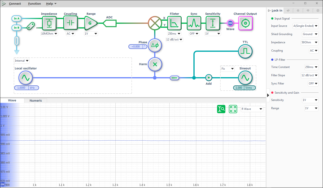
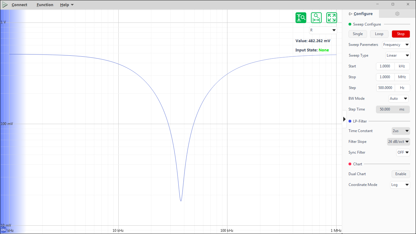
The OE2041 has three interfaces, RS232, USB2.0 and Ethernet, which can be used to set up all the functions of the instrument, ensuring that the user can effectively use all the test functions of the OE2041 on the control computer, including setting up the reasonable control parameters of the instrument and reading the data measured by the instrument. At the same time, in order to make it more convenient for the user to use the various functions, the instrument is equipped with a corresponding LabVIEW programme, which can read and save the measured data in real time. This makes the OE2041 easy to use in complex scientific experiments.
Voltage Input Mode Single-ended or Differential
Full-scale Sensitivity 1 nV to 1 V in a 1-2-5 sequence
Impedance
Voltage 50 Ω // 5pF or 10 MΩ // 5pF,AC or DC coupled
C.M.R.R >70 dB to 100 Hz
>50 dB to 100 kHz
Dynamic reserve >120 dB
Gain accuracy 0.5% typ(<1MHz), 3% max
Voltage Noise 3nV/√Hz at 999.99 kHz
Line filters 50/60 Hz and 100/120 Hz
Gounding BNC shield can be grounded or floated via 10 kΩ to ground
Reference Channel
Input
Frequency range 10 uHz to 60 MHz
Reference input TTL or Sine
Input impedance 1 MΩ
Square reference level VIH>3V, VIL<0.5V
Sine reference signal >1 Hz
> 400 mVpp
Phase
Resolution 1udeg
Absolute phase error <1°
Relative phase error <1 mdeg
Phase noise Internal ref. Synthesized, <0.0001 deg at1 kHz
External ref. 0.001 deg at 1 kHz (100 ms time constant, 12 dB/oct)
Drift <0.01 deg/℃ below 100 kHz
<0.1 deg/℃ above 100 kHz
Harmonic detection 2F, 3F, …nF to 60 MHz (n<32,767)
Acquisition time Internal Ref. Instantaneous acquisition
External Ref. (2 cycles + 5 ms) or 40 ms,whichever is larger
Demodulator
Number of demodulators 4
Stability
Digital outputs no zero drift on all setting
Display no zero drift on all setting
Analog outputs <5 ppm/℃ for all dynamic reserve settings
Harmonic rejection -90 dB
Time constants 30 ns to 4.4 ks (6,12,18,24,30,36,42,48 dB/oct rolloff)
Synchronous filters Available below 200 Hz(18,24,30,36,42,48 dB/oct rolloff)
Internal Oscillator
Frequency 10 uHz to 60 MHz
Accuracy 2 ppm + 10 µHz
Resolution 1 nHz
Disrortion -80 dBc (f<10 kHz),-60 dBc (f>1 MHz)
Amplitude 1uVrms to 1 Vrms ( Resolution:1 uVrms)
Accuracy 0.5%
Stability 50 ppm/℃
Sine Outputs Sine signal,output impedance 50 Ω
TTL Outputs 5V TTL/CMOS level,output impedance 50Ω
AUX Inputs and Outputs
AUX Inputs
Function 4 Channel Inputs
Amplitude ±10 V,1 mV resolution ratio
Impedance 1 MΩ
AUX/CH Outputs
Function 4 Channel Outputs
Amplitude ±10 V,0.1 mV resolution ratio
Drive current 30mA max
Display
Screen 5.6 inch, 640×480 TFT
Screen format Single or dual display
Display quantities Each display shows one trace,
traces can be defined as X,Y,R,θ
Display types Numerical form, bar graph
Interfaces
USB2.0
RS-232(DB-9)
1000Mbps Enthernet
General
Power requirements
Voltage 220-240 V AC
100-120 VAC(optional)
Frequency 50/60 Hz
Power 60 W
Power supply rejectio 70dB@1MHz
Weight 12 KG
Dimensions
Width 448 mm
Depth 513 mm
Height
With feet 148 mm
Scanning Microscope AFM, STM, SPM
Materials Science Carrier mobility, Carrier density, Hall effect, Ultrasonic materials
Transport Measurement Conductivity measurement, Impedance measurement
Noise Represents Noise density, Cross-correlation measurement
Optical Experiment Spectral analysis, Spectral measurement, THz measurement, TDLAS
Sensor Measuring Gyroscope, Photoelectric sensor, Resonator, Accelerometer
Magnetic Sensor SQUIDs, NV color center, Atomic Magnetometer, VSM
Biomedical Microfluidic
Lock-in Amplifier
Parametric Sweeper
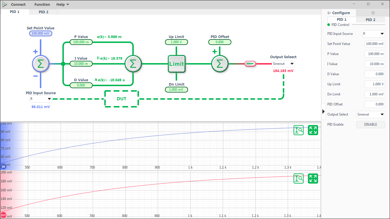
PID Controllers
FFT Spectrum Analyzer

Oscilloscope
